This is the PIC program that is used to run this robotic arm.
'****************************************************************
'* Name : SSC-TEST1.BAS *
'* Author : Nik MJ *
'* Notice : Copyright (c) 2007*
'* : All Rights Reserved *
'* Date : 9/17/2007 *
'* Version : 1.0 *
'* Notes : 9/17/2007 *
'* : Program to test the serial servo controller board *
'* 10/30/2007 *
'* Modify to run 4 servos automatically without PC *
'* (stand alone PIC controller) to lift small *
'* mooncakes from one platform to another at 90 *
'* degree adjacent *
'****************************************************************
'Set Tris State Register A and B
TRISB = %11111111 'Set register B ports all as output
TRISA = 001100
DEFINE OSC 4 'Set Oscillator running at 4MHz
Button_1 VAR PORTA.2
Button_2 VAR PORTA.3
Led VAR PORTA.4
'Loop Sentinel
I0 VAR BYTE
I1 VAR BYTE
I2 VAR BYTE
I3 VAR BYTE
I4 VAR BYTE
I5 VAR BYTE
I6 VAR BYTE
I7 VAR BYTE
'Initalize all servos port out to LOW
LOW PORTB.0
LOW PORTB.1
LOW PORTB.2
LOW PORTB.3
LOW PORTB.4
LOW PORTB.5
LOW PORTB.6
LOW PORTB.7
'Servos
S0 VAR BYTE 'Base
S1 VAR BYTE 'Left Shoulder NOT USED
S2 VAR BYTE 'Right Shoulder NOT USED
S3 VAR BYTE 'Elbow
S4 VAR BYTE 'Left Wrist NOT USED
S5 VAR BYTE 'Right Wrist NOT USED
S6 VAR BYTE 'Wrist Rotation
S7 VAR BYTE 'Gripper
'Servos Default Data Position
S0 = 135
S1 = 111
S2 = 144
S3 = 125
S4 = 127
S5 = 127
S6 = 114
S7 = 40
'Initialize buttons and Led
LOW Button_1
LOW Button_2
LOW Led
Start:
Pos_0: 'Default rest postion
FOR I0 = 1 TO 1000
HIGH Led
S0 = 135
S3 = 125
S7 = 40
PULSOUT PORTB.0,S0
PULSOUT PORTB.3,S3
PULSOUT PORTB.6,S6
PULSOUT PORTB.7,S7
NEXT I0
LOW Led
Pos_1: 'Move Elbow downward
FOR I1 = 1 TO 1000
HIGH Led
S0 = 135
S3 = 168
S7 = 40
PULSOUT PORTB.0,S0
PULSOUT PORTB.3,S3
PULSOUT PORTB.6,S6
PULSOUT PORTB.7,S7
NEXT I1
LOW Led
Pos_2: 'Close Gripper inward
FOR I2 = 1 TO 1000
HIGH Led
S0 = 135
S3 = 168
S7 = 85
PULSOUT PORTB.0,S0
PULSOUT PORTB.3,S3
PULSOUT PORTB.6,S6
PULSOUT PORTB.7,S7
NEXT I2
LOW Led
Pos_3: 'Move Elbow upward (Lift the load)
FOR I3 = 1 TO 2000
HIGH Led
S0 = 135
S3 = 125
S7 = 85
PULSOUT PORTB.0,S0
PULSOUT PORTB.3,S3
PULSOUT PORTB.6,S6
PULSOUT PORTB.7,S7
NEXT I3
LOW Led
Pos_4: 'Rotate Base 90CCW
FOR I4 = 1 TO 2000
HIGH Led
S0 = 220
S3 = 125
S7 = 85
PULSOUT PORTB.0,S0
PULSOUT PORTB.3,S3
PULSOUT PORTB.6,S6
PULSOUT PORTB.7,S7
NEXT I4
LOW Led
Pos_5a: 'Move Elbow downward
FOR I5 = 1 TO 1000
HIGH Led
S0 = 220
S3 = 145
S7 = 85
PULSOUT PORTB.0,S0
PULSOUT PORTB.3,S3
PULSOUT PORTB.6,S6
PULSOUT PORTB.7,S7
NEXT I5
LOW Led
Pos_5b: 'Move Elbow downward (Place the load)
FOR I5 = 1 TO 1000
HIGH Led
S0 = 220
S3 = 158
S7 = 85
PULSOUT PORTB.0,S0
PULSOUT PORTB.3,S3
PULSOUT PORTB.6,S6
PULSOUT PORTB.7,S7
NEXT I5
LOW Led
Pos_6: 'Open Gripper outward (Release the load)
FOR I6 = 1 TO 750
HIGH Led
S0 = 220
S3 = 158
S7 = 40
PULSOUT PORTB.0,S0
PULSOUT PORTB.3,S3
PULSOUT PORTB.6,S6
PULSOUT PORTB.7,S7
NEXT I6
LOW Led
Pos_7: 'Move Elbow upward (Job finish)
FOR I7 = 1 TO 1000
HIGH Led
S0 = 220
S3 = 125
S7 = 40
PULSOUT PORTB.0,S0
PULSOUT PORTB.3,S3
PULSOUT PORTB.6,S6
PULSOUT PORTB.7,S7
NEXT I7
LOW Led
Pos_8: 'Return to default rest postion
FOR I0 = 1 TO 1800
HIGH Led
S0 = 135
S3 = 125
S7 = 40
PULSOUT PORTB.0,S0
PULSOUT PORTB.3,S3
PULSOUT PORTB.6,S6
PULSOUT PORTB.7,S7
NEXT I0
LOW Led
IF Button_1 = 0 AND Button_2 = 0 THEN GOTO Start 'Continue
IF Button_1 = 1 AND Button_2 = 0 THEN GOTO Pos_8 'Hold
IF Button_2 = 1 AND Button_1 = 1 THEN 'Restart
LOW Button_1
LOW Button_2
GOTO Start
ENDIF
IF Button_1 = 0 AND Button_2 = 1 THEN End_Loop 'End
End_Loop:
END
Click here to download this pdf file.


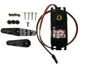
 As you can see, I put some remark on S3S4 simply because they are meant for double servos. They would be tested later on since I realized that these Bizchips servos can opened up to more than 180 degree as Futaba S3003. This is meaning that there would be some calculation error for Clockwise and Counter clockwise rotation if I were to use the similar formula with Futaba S3003. As such I will delay the test, and instead I will proceed with the small conveyors installation first.