Thursday, November 22, 2007

Test of the Bizchip Servos

Since this time we are using two different kind of servos, thus it is necessary to check the new servos behavior prior to utilising them fully. As such I wrote down the program using PIC to test the Bizchips servos that are used for Base, Wrist, Wrist Rotation and the Gripper.
The reason these four degrees of freedom are chosen is simply because all of them are using a single servo as the mechanism to move.
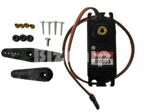
As you can see, I put some remark on S3S4 simply because they are meant for double servos. They would be tested later on since I realized that these Bizchips servos can opened up to more than 180 degree as Futaba S3003. This is meaning that there would be some calculation error for Clockwise and Counter clockwise rotation if I were to use the similar formula with Futaba S3003. As such I will delay the test, and instead I will proceed with the small conveyors installation first.

Wednesday, November 21, 2007

Pick & Place Using 6 DOF Robotic Arm

As the parts required for the Robotic Arm are available already, now we can start to design and built the second RA. This time we are going to built a 6 degrees of freedom RA. This RA will make full use of 6 pieces of Bizchip 13 kgcm torque servos as well as another 2 pieces of Futaba S3003 servos.

Design Concept
There would be two small conveyors that would be use to simulate the actual production conveyors. The first one is supposed to bring the moon cakes and stop at one position, waiting to be pick up by the RA. The second conveyor would carry the empty tray and stop at waiting position. Once both of the moon cake and tray are ready, the RA arm would be initiated from rest position to pick the moon cake and place it inside the tray. The process would continue on and on. In case of emergency, the RA would be reset to rest position and both of the conveyors would stop running. The whole RA body would use aluminum and the base would be moving on 4 roller weight distribution bearing taken from Tamiya ball caster. The gripper would use single movement as for the time being, the making of double gripper would require quite extensive mechanical job.

Design Objectives
The RA should be able to lift the moon cake load to about 260gm.
The RA should be fast enough to work in picking up the moon cake from one conveyor to another and place it inside a tray.
Whenever the emergency button is pressed, the RA should reset to rest position
The moon cake quality should not be affected by RA gripper

Design Constraints
Since the biggest servo could only lift 13kg for 1cm, thus if the shoulder is about to reach 50 cm, then the RA weight must be zero as the 260gm is the required load. Because of this, the weight of the RA should be minimized to allow maximum lifting capacity.
Due to this reason, we planned to use a couple of servos for shoulder as well as the elbow. For the rest of the freedoms, one servo is enough as the length is minimum.

6 DOF
The 6 degrees of freedom are :
i- Base
ii- Shoulder
iii- Elbow
iv-Wrist
v-Wrist Rotation
vi- Gripper

Softwares & Hardwares
As the previous RA, this RA would use Serial Servo Controller (SSC) to run the mechanism. Instead of running directly through a PC, this RA would use a PIC micro controller chip that has been programmed by EPICA hex code where the source code is being written using MicroCode. With this combination, the RA would only need a 9VDC for SSC and 6VDC for the RA servos to run.
As for laboratory prototype, the control of the small conveyors would be done by relays (MY4N & LY2) hardwires. These relays are wired in such a way that they use sensors as input and use their contacts to send signal to the RA to ON and OFF as well as to switch ON and OFF the small conveyors AUTOMATICALLY.
The DC box power supply would be used to supply the DC to the electronics components as well as the relays. As for the SSC, a separate 6VDC power supply would be used as the servos required a higher rating current to work efficiently.

Tuesday, November 06, 2007

Second Stage Parts Acquirement

Servo Motor
Since the Jumbo Servo is not available locally, we decided to purchase the local Bizchip 13kgcm torque servos for seven pieces to built the next working robotic arm that should be abled to lift at least 200gram load. This is the one we purchased for RM90 each.
Ball Bearing Roller
As for the robot base, this time we upgrade a bit to reduce the friction by using the Tamiya roller caster costing RM18 per pair. We used two pairs for our base to balance the load of the robotic arm. This is the one we purchased.

Thursday, November 01, 2007

Mini Robotic Arm Test Run Video Clip


This is the PIC program that is used to run this robotic arm.
'****************************************************************
'* Name : SSC-TEST1.BAS *
'* Author : Nik MJ *
'* Notice : Copyright (c) 2007*
'* : All Rights Reserved *
'* Date : 9/17/2007 *
'* Version : 1.0 *
'* Notes : 9/17/2007 *
'* : Program to test the serial servo controller board *
'* 10/30/2007 *
'* Modify to run 4 servos automatically without PC *
'* (stand alone PIC controller) to lift small *
'* mooncakes from one platform to another at 90 *
'* degree adjacent *
'****************************************************************
'Set Tris State Register A and B
TRISB = %11111111 'Set register B ports all as output
TRISA = 001100

DEFINE OSC 4 'Set Oscillator running at 4MHz

Button_1 VAR PORTA.2

Button_2 VAR PORTA.3
Led VAR PORTA.4

'Loop Sentinel

I0 VAR BYTE
I1 VAR BYTE
I2 VAR BYTE
I3 VAR BYTE
I4 VAR BYTE
I5 VAR BYTE
I6 VAR BYTE
I7 VAR BYTE

'Initalize all servos port out to LOW

LOW PORTB.0
LOW PORTB.1
LOW PORTB.2
LOW PORTB.3
LOW PORTB.4
LOW PORTB.5
LOW PORTB.6
LOW PORTB.7

'Servos

S0 VAR BYTE 'Base
S1 VAR BYTE 'Left Shoulder NOT USED
S2 VAR BYTE 'Right Shoulder NOT USED
S3 VAR BYTE 'Elbow
S4 VAR BYTE 'Left Wrist NOT USED
S5 VAR BYTE 'Right Wrist NOT USED
S6 VAR BYTE 'Wrist Rotation
S7 VAR BYTE 'Gripper

'Servos Default Data Position

S0 = 135
S1 = 111
S2 = 144
S3 = 125
S4 = 127
S5 = 127
S6 = 114
S7 = 40

'Initialize buttons and Led

LOW Button_1
LOW Button_2
LOW Led

Start:

Pos_0: 'Default rest postion
FOR I0 = 1 TO 1000
HIGH Led
S0 = 135
S3 = 125
S7 = 40
PULSOUT PORTB.0,S0
PULSOUT PORTB.3,S3
PULSOUT PORTB.6,S6
PULSOUT PORTB.7,S7
NEXT I0
LOW Led

Pos_1: 'Move Elbow downward

FOR I1 = 1 TO 1000
HIGH Led
S0 = 135
S3 = 168
S7 = 40
PULSOUT PORTB.0,S0
PULSOUT PORTB.3,S3
PULSOUT PORTB.6,S6
PULSOUT PORTB.7,S7
NEXT I1
LOW Led

Pos_2: 'Close Gripper inward

FOR I2 = 1 TO 1000
HIGH Led
S0 = 135
S3 = 168
S7 = 85
PULSOUT PORTB.0,S0
PULSOUT PORTB.3,S3
PULSOUT PORTB.6,S6
PULSOUT PORTB.7,S7
NEXT I2
LOW Led

Pos_3: 'Move Elbow upward (Lift the load)

FOR I3 = 1 TO 2000
HIGH Led
S0 = 135
S3 = 125
S7 = 85
PULSOUT PORTB.0,S0
PULSOUT PORTB.3,S3
PULSOUT PORTB.6,S6
PULSOUT PORTB.7,S7
NEXT I3
LOW Led

Pos_4: 'Rotate Base 90CCW

FOR I4 = 1 TO 2000
HIGH Led
S0 = 220
S3 = 125
S7 = 85
PULSOUT PORTB.0,S0
PULSOUT PORTB.3,S3
PULSOUT PORTB.6,S6
PULSOUT PORTB.7,S7
NEXT I4
LOW Led

Pos_5a: 'Move Elbow downward

FOR I5 = 1 TO 1000
HIGH Led
S0 = 220
S3 = 145
S7 = 85
PULSOUT PORTB.0,S0
PULSOUT PORTB.3,S3
PULSOUT PORTB.6,S6
PULSOUT PORTB.7,S7
NEXT I5
LOW Led

Pos_5b: 'Move Elbow downward (Place the load)

FOR I5 = 1 TO 1000
HIGH Led
S0 = 220
S3 = 158
S7 = 85
PULSOUT PORTB.0,S0
PULSOUT PORTB.3,S3
PULSOUT PORTB.6,S6
PULSOUT PORTB.7,S7
NEXT I5
LOW Led

Pos_6: 'Open Gripper outward (Release the load)

FOR I6 = 1 TO 750
HIGH Led
S0 = 220
S3 = 158
S7 = 40
PULSOUT PORTB.0,S0
PULSOUT PORTB.3,S3
PULSOUT PORTB.6,S6
PULSOUT PORTB.7,S7
NEXT I6
LOW Led

Pos_7: 'Move Elbow upward (Job finish)

FOR I7 = 1 TO 1000
HIGH Led
S0 = 220
S3 = 125
S7 = 40
PULSOUT PORTB.0,S0
PULSOUT PORTB.3,S3
PULSOUT PORTB.6,S6
PULSOUT PORTB.7,S7
NEXT I7
LOW Led

Pos_8: 'Return to default rest postion

FOR I0 = 1 TO 1800
HIGH Led
S0 = 135
S3 = 125
S7 = 40
PULSOUT PORTB.0,S0
PULSOUT PORTB.3,S3
PULSOUT PORTB.6,S6
PULSOUT PORTB.7,S7
NEXT I0
LOW Led

IF Button_1 = 0 AND Button_2 = 0 THEN GOTO Start 'Continue

IF Button_1 = 1 AND Button_2 = 0 THEN GOTO Pos_8 'Hold
IF Button_2 = 1 AND Button_1 = 1 THEN 'Restart
LOW Button_1
LOW Button_2
GOTO Start
ENDIF
IF Button_1 = 0 AND Button_2 = 1 THEN End_Loop 'End

End_Loop:

END


Click here to download this pdf file.

Wednesday, October 24, 2007

Conveyor Project


8255PPI Project


8255 Datafiles
All About 8255

USB I/O 24mk III Project

4 Degrees Of Freedom Mini Robotic Arm

Overview
Due to servo motors availability, we built a mini Robotic Arm using just 4 pieces of Futaba S3003 that make up a 4 DOF Robotic Arm.

Mini Robotic Arm Side View
The first one is used for the base. The second one is used for the elbow. The third one is used for the wrist rotation. And the last one is used for the single movement gripper. The arm base is made of plastic, while the rest of the body is being made of aluminum. The whole arm is rested on a piece of wood. The objective of the design is to learn the robotic arm concept in pick and place procedures industrially.
Mini Robotic Arm Top View

Design Concept
For the base, we use some screw heads topped with some grease for fine movement as a replacement for the weight distribution bearing. This is simply because the part is not locally available in the market. Yet even if we
were to order from oversea, the simple base would cost more than RM400, which is too costly for simple project.
For elbow and wrist rotation, we share the same frame to minimize weight due to the limited torque of the standard servos.
Mini Robotic Arm elbow and wrist rotation
As for the gripper, we redesigned a simple single movement gripper to reduce the size. The same design also help to reduce the total weight for the elbow to lift.
Mini Robotic Arm gripper
The four servos are connected to the Serial Servo Controller Board through a 25pin female Centronics connector.
Serial Servo Controller
The reason to use 25 pins is simply the SSC board are designed to control up to 8 servos, where each servo is using 3 pins . Thus , the same connection can be used for later 8 DOF Robotic Arm project as well.
To give some weight for support, the base is pinned to a square wooden base. While helping the Robotic Arm (RA) to stand firmly, it allows easier handling for the arm as well.

Design Analysis
The movement of the base and elbow are not that smooth enough. Better fittings with proper alignment are needed for improvement. Yet, the torque for standard servos seems like not strong enough for the base. Perhaps to carry heavier load, a higher grade servo is required.

The wrist rotation is quite OK as it doesn't affect the whole process so much. However, for the gripper it is having some difficulty in gripping the load properly due to single grip. The best is to have more than one movement gripper, although that might burden the base and elbow .
In short, this mini RA is quite OK for a start. There are many sections that could be improved especially once all the necessary items required are available later on. Next, the actual implementation place should be clarified so that a proper design can be done.
Mini Robotic Arm Lifting a Load

Design Upgrade
Since the main objective for this project is achieved (built RA that is serially controlled by a PC), we are going into next stage ASAP. In the next stage we are going to reprogram the RA to do specific job automatically. This will require some PIC reprogramming of the job sequence for the servos to work syncronously with each other without manual control from the PC serial interface. This is to enable the RA to run independently with a preprogrammed job.
In order to do this, some manual job to record the all servos position data in each sequence are required. It will takes some time as the mechanism funny vibrations are not yet fully solved. As such a more thorough study of the the RA concept are needed so that a better quality movement can be achieved.

Mini Robotic Arm At Work

Tuesday, October 02, 2007

Another replacement for CS-600 (Hitec HS-5955TG)

I found another model Hitecc HS5955TG a digital servo that could be used to replace the CS-600. This one is digital type. So the previous model Futaba S3306 is now out of question since that one is analog type. This is how its looks like.One more thing is that CS-600 works on 90 degree angle, this Hitec is the same as well.The HSC-5955TG is the ultimate standard size servo period! This servo was specifically designed for use in giant scale aircraft and high performance R/C vehicles. With an amazing 333 oz-in. of torque and Titanium gears packed in a standard size case it out performs any other servo in the marketplace. We also include a heavy duty carbon brush coreless motor wrapped in a metal heatsink center case to handle the harshest environment. The new upper case incorporates hardened pins for the gears with oilite bushings to allow these series of servos to take repeated punishment. Topping it off with gold-plated connectors, heavy duty wire and 8 rubber rings in the case offering excellent water and fuel resistance, the HSC-5955TG servo is in a league by itself. We offer the HS-5955TG servo in several configurations, 90° stock rotation, 180° modified rotation, continuous rotation (potentiometer is left outside the servo case) and reverse rotation.

*Digital servos do not need to be programmed to operate. They work great right out of the box and purchasing a programmer is not neccessary.

HS-5955TG Detailed Specifications
Control System: +Pulse Width Control 1500usec Neutral
Required Pulse: 4.8-6.0 Volt Peak to Peak Square Wave
Operating Voltage Range: 4.8-6.0 Volts
Operating Temperature Range: -20 to +60°C (-68F to +140F)
Operating Speed (4.8V): 0.19 sec/60° at no load
Operating Speed (6.0V): 0.15 sec/60° at no load
Stall Torque (4.8V): 249.96 oz-in. (18 kg.cm)
Stall Torque (6.0V): 333.29 oz-in. (24 kg.cm)
Standing Torque (4.8V): 324.95 oz-in. (23.4 kg.cm) 5° deflection
Standing Torque (6.0V): 433.27 oz-in. (31.2 kg.cm) 5° deflection
Operating Angle: 60° one side pulse traveling 400usec
360 Modifiable: Yes
Direction: Clockwise/Pulse Traveling 1500 to 1900 usec
Idle Current Drain (4.8V): 3mA at stop
Idle Current Drain (6.0V): 3mA at stop
Current Drain (4.8V): 220mA/idle and 3.4 amps at lock/stall
Current Drain (6.0V): 300mA/idle and 4.2 amps at lock/stall
Dead Band Width: 2 usec
Motor Type: Coreless Metal Brush
Potentiometer Drive: 6 Slider Indirect Drive
Bearing Type: Dual Ball Bearing MR106
Gear Type: 4 Titanium Gears
Connector Wire Length: 7" (178mm)
Dimensions: 1.57" x 0.78"x 1.45" (40 x 20 x 37mm)
Weight: 2.18oz (62g)

Monday, September 24, 2007

Replacement for CS-600 (Futaba S3306)

Since the local vendor that used to supply the Futaba S3003 cannot supply the Cirrus CS-600 Jumbo FET servo, I search and found that the Futaba S3306 carries almost same characteristics with CS-600. This means that I can use it to replace the Cirrus servo.

Futaba S3306 Hi-Torque Servo

The largest servo in the futaba range, the S3306 offers a full 25.0 kg/cm torque together with excellent speed, and is water resistant, so is perfectly suited to larger scale models and robots.

  • Torque: 25.0 kg/cm
  • Speed: 0.16 sec/60°
  • Dimensions: 66 x 30 x 57.1mm
  • Weight: 128g

  • Here is how this servo looks like.
    This is the Futaba S3306 High Torque/High Speed Servo for 1/5 Scale Cars.


    FEATURES: Ideal steering servo for 1/5 scale vehicles
    High speed
    High torque
    Dual ball bearings
    One year limited warranty


    INCLUDES: Futaba S3306 1/5 scale High Torque/High Speed Servo
    Two grommets
    Four screws
    Four eyelets
    Two White plastic servo horns (arms)
    1- "X" 3.8" (98mm) diameter
    1- "6-arm" 3.5" (88mm) diameter


    SPECS: 4.8V 6V
    Torque: 266.5 oz-inch 333 oz-inch
    Speed: .20 sec @ 60° .16 sec @ 60°


    Size- 2.6 x 1.18 x 2.25 in. (66x30x57mm)
    Weight- 128g (4.52oz)
    Output Shaft Diameter: 8mm

    This servo can be purchased online at Active Robot or direct to Futaba.


    Saturday, September 22, 2007

    Mechanical Parts Differences

    We are having a big problem now because our local suppliers (Vanguard, Blitzlogic)cannot supply this big Jumbo Pro Cirrus CS-600 Servo Motor. They dont even have the other brand like Hitecc or Futaba for about the same specs with this Cirrus. As such we might have to source overseas.

    Next the Lazy Susan weight distribution bearing. The one that we have is not the same size. Yet the middle hole is too small compare to Lazy Suzan. As such installing the new Jumbo Servo in the middle will require platforms for top and bottom. This will increase the height that might affect the standard height of the servo stud. However for the time being we cannot finalize ot yet since we do not have the actual Jumbo servo dimension yet.

    Next for the bodykit, the standard thicjness of the flat aluminum available is 3mm which is about 1/8". This is too thick to bend and quite heavy for jumbo servo. Due to this reason, we have to modify the bodykit design and dimension again to fits the available items.


    Tuesday, September 18, 2007

    Serial Servo Controller Part2

    PIC SSC
    Write the PIC code using MicroCode and transfer the HEX code generated from SSC.BAS to PIC chip 16F84A using EPICWIN program. This is the code that I use :
    '*************************************************************************************
    TRISB =000000

    TRISA=001101

    DEFINE 0SC 4
    include "modedefs.bas"

    Led VAR PORTA.4
    Baud CON N2400
    Com_In VAR PORTA.0
    Com_Out VAR PORTA.1
    Control VAR BYTE
    Slider VAR BYTE

    Sync VAR BYTE
    I VAR BYTE
    S0 VAR BYTE
    S1 VAR BYTE
    S2 VAR BYTE
    S3 VAR BYTE
    S4 VAR BYTE
    S5 VAR BYTE
    S6 VAR BYTE
    S7 VAR BYTE

    LOW PORTB.0
    LOW PORTB.1
    LOW PORTB.2
    LOW PORTB.3
    LOW PORTB.4
    LOW PORTB.5

    LOW PORTB.6
    LOW PORTB.7
    HIGH Led

    S0 = 127
    S1 = 111
    S2 = 144
    S3 = 65
    S4 = 127
    S5 = 127
    S6 = 127
    S7 = 127

    Start:

    SERIN Com_In,Baud,7,Set_Pos,[255],Slider,Control
    SEROUT Com_Out,Baud,[Slider,Control]

    IF Slider = 0 THEN S0 = Control


    IF Slider = 1 THEN
    S1=Control
    S2=254-S1
    ENDIF

    IF Slider = 2 THEN S3 = Control

    IF Slider = 1 THEN
    S4=Control
    S5=254-S4
    ENDIF

    IF Slider=4 THEN S6=Control

    IF Slider=5 THEN S7=Control

    Set_Pos:

    PULSOUT PORTB.0,S0
    PULSOUT PORTB.1,S1
    PULSOUT PORTB.2,S2
    PULSOUT PORTB.3,S3
    PULSOUT PORTB.4,S4
    PULSOUT PORTB.5,S5
    PULSOUT PORTB.6,S6
    PULSOUT PORTB.7,S7

    GOTO Start
    '***************************************************************************************

    Futaba S3003 Test
    Connect the four Futaba S3003 standard servo motors to R4, R5, R6, R7 of the PIC chip output.


    VB SSC
    As the actual slider program is quite long and time consuming to program, therefore for test purposes I just simply used the downloaded version of the executable file that I download from http://www.thinkbotics.com/book_support.

    Monday, September 17, 2007

    Serial Servo Controller Part1

    The first step toward completing the robotic arm project is to make sure the PIC Chip 16F84A gadgets are all OK. This will involve some engineering work from software, hardware, and mechanical job. As for first stage since I already got the EPICA programmer and MicroCode software, what I have to do is to write the test program for the Serial Servo Controller. As for information, the software for EPICA is called EPICWIN.EXE and the software for PIC is called MicroCode.

    The code is first being programmed using MicroCode. Next, once all OK. the code is compiled and will produced a HEX code that will be burnt onto the PIC chip. The HEX code later is opened using EPICWIN where later on it will be programmed on to the PIC chip 16F84A.

    The intermediate device that is used to transfer the HEX code from PC to PIC chip is called a EPICA PROGRAMMER. It is connected to the PC using 25P DSUB connector through parallel port.

    Software Test
    This is the code for ssc-test.bas that I used to program the Serial Servo Controller
    '----------------------------------------------------------------------------------------

    'NAME : ssc-test.bas
    'COMPILER : PicBasic Pro - microEngineering Labs
    'NOTES : Program to test the serial servo controller board
    '----------------------------------------------------------------------------------------
    TRISB=000000
    TRISA=001101
    DEFINE OSC 4
    Button_1 VAR PORTA.2
    Button_2 VAR PORTA.3
    Led VAR PORTA.4
    I VAR BYTE

    Low Led
    Start:

    FOR I=1 TO 10
    HIGH Led
    PAUSE 200
    LOW Led
    PAUSE 200
    NEXT I
    Loop:
    LOW Button_1
    LOW Button_2

    IF Button_1 = 1 THEN HIGH Led
    IF Button_2=1 THEN LOW Led

    GOTO Loop
    END

    The code is programmed using MicroCode software that later on after compiling will create a HEX file. This HEX file is used by EPICWIN to burnt onto the PIC chip.


    Circuit Test
    The circuit is quite simple. However to shorten the R&D period I just used the one Matthew installed on the prototype board. After correcting some wiring mistakes I managed to power it on. Firstly I thought the input DC power supply got problem because the EPICA LED is OFF. Upon checking, I found the 9V DC supply is OK. As suggested by the book author, I managed to drive the SSC circuit LED to blink 10X continuosly. Next I also managed to trigger button 1 to ON the LED and button 2 to turn OFF the same LED. In fact , this means that the assembled circuit is OK and all the parts used are OK as well. Next it also meant that I successfully burnt the program to PIC chip 16F84A. One more, this shows that the EPICA programmer is working fine. This is how it woll looks like once completed.

    Saturday, August 11, 2007

    Robotic - MPLAB

    What is MPLAB IDE?
    MPLAB Integrated Development Environment (IDE) is a free, integrated toolset for the development of embedded applications employing Microchip's PIC® and dsPIC® microcontrollers. MPLAB IDE runs as a 32-bit application on MS Windows®, is easy to use and includes a host of free software components for fast application development and super-charged debugging. MPLAB IDE also serves as a single, unified graphical user interface for additional Microchip and third party software and hardware development tools. Moving between tools is a snap, and upgrading from the free software simulator to hardware debug and programming tools is done in a flash because MPLAB IDE has the same user interface for all tools.


    Don't know where to start?

    Download MPLAB IDE and use the tutorial in the MPLAB IDE Quick Start manual at the bottom of this page to explore how easy it is to create an application. Write assembly code, build and assemble your project with MPLAB's wizards, then test your code with the built-in simulator and debugger. When you are ready to test your own application, select one of our
    low-cost debugger/programmers to program a device and analyze your hardware.

    Want to write your code in C?

    Choose MPLAB C18, the highly optimized compiler for the PIC18 series microcontrollers, or try the newest Microchip's language tools compiler, MPLAB C30, targeted at the high performance PIC24 and dsPIC digital signal controllers. Or, use one of the many products from third party language tools vendors. Most integrate into MPLAB IDE to function transparently from the MPLAB project manager, editor and debugger.


    Learn about MPLAB IDE with on-line seminars?

    See the Microchip Web Seminars for up-to-date information on using Microchip products. The archive section contains the
    Introduction to MPLAB IDE Web Seminar for a tutorial that will get you started quickly with MPLAB projects. A seminar entitled Tips and Tricks in MPLAB IDE identifies many of the latest features to make code development even easier. The Visual Device Initializer is demonstrated in a VDI Seminar. There is also an Overview of Microchip Development Tools Seminar, and a walk-through of the powerful features of the simulator and stimulus generator in the MPLAB SIM Seminar.

    MPLAB IDE features include:

    Flexible customizable programmer's text editor
    Fully integrated debugging
    with right mouse click menus for breakpoints, trace and editor functions
    Tabbed editor option or separate source windows
    Recordable macro
    Context sensitive color highlighting for assembly, C and BASIC code readability
    Auto indent
    Choice of fonts
    Adjustable tab size
    Custom tool bars
    Auto indent tab to space conversion
    Brace match
    Comment/uncomment block
    Bookmarks
    Code folding/browsing to expand and collapse areas of code for more efficient browsing
    Find in files
    Find in project
    Mouse over variable to instantly evaluate the contents of variables and registers
    Set breakpoints directly in editor to instantly make changes and evaluate their effects
    Set tracepoints directly in editor to quickly mark points for trace collection of real time activity
    Run to cursor

    Set PC to cursor


    Simple, powerful Source level debugging
    Auto alignment of breakpoints after source code modification
    Mouse-over variable inspection
    Drag and drop variables to watch windows
    Watch variables, structures and arrays
    Mixed source code/disassembly view
    Stack symbolic return label display
    Automatic single-step "animate" feature
    Pass counts and break on PIC18F, PIC24 and dsPIC file register R/W for MPLAB ICD 2

    Step-Out-Of function

    Custom hot keys
    Powerful simulator stimulus generator

    Trace to source correlation to compare real time data collected with original source code and comments


    Latest Production Release:
    MPLAB IDE v7.60
    New in MPLAB IDE v7.60:
    The most recent full release of MPLAB IDE v7.60 introduces these new features:


    MPLAB IDE
    - Expanded trace captures and displays more data using a disk buffer up to 2G byte. - Multiple path inclusions in project build options replaces the previous single line, semi comma delimited entry. - ASM30 files can be processed through the Microchip C preprocessor so that C style directives embedded in assembly files are converted by the preprocessor. - Relative paths are now supported in the Project Wizard. - Standard “make files” can be generated for all processors. - The DMCI (Data Monitor and Control Interface) has new sliders, split window panes, data capture graph buffers, and a number of other enhancements.

    MPLAB REAL ICE
    - MPLAB REAL ICE can collect and display data in the DMCI. - PIC18 support, software breakpoints for 16-bit devices, and complex triggers are now supported

    MPLAB SIM
    - Simulator code coverage is re-designed in the simulator to be exactly like in-circuit emulators

    New device support:
    For full specific device support listings and details on changes to MPLAB IDE v7.60, refer to the associated release notes.


    New in MPLAB IDE v7.61 Interim Release:

    Docking Windows: This release introduces an improved facility for standard docking windows. .

    REAL ICE Stopwatch:
    REAL ICE now provides an MPLAB ICE-style stopwatch.

    REAL ICE Complex Breakpoints: Breakpoints can be grouped by sequencing or combined with a Boolean AND operation.
    Code Folding in Assembly Language: A comment with an open brace (;}) indents the following block. A comment with a closing brace (;{) out-dents the following block.
    Reading Device ID via PM3 utilities: A new switch has been added to PM3CMD to read the Device ID of the device in the programmer.

    Calibration Memory programming in PRO MATE II: An MPLAB ICD 2-style facility to program calibration memory is now presented in the PRO MATE II menus.

    New part support. Check the Release Notes for support by the individual components


    New in MPLAB IDE v7.61:

    The most recent interim release of MPLAB IDE v7.61 introduces these new features over v7.60
    Docking Windows: This release introduces an improved facility for standard docking windows. .
    REAL ICE Stopwatch:
    REAL ICE now provides an MPLAB ICE-style stopwatch.
    REAL ICE Complex Breakpoints:
    Breakpoints can be grouped by sequencing or combined with a Boolean AND operation.
    Code Folding in Assembly Language:
    A comment with an open brace (;}) indents the following block. A comment with a closing brace (;{) out-dents the following block.
    Reading Device ID via PM3 utilities:
    A new switch has been added to PM3CMD to read the Device ID of the device in the programmer.
    Calibration Memory programming in PRO MATE II:
    An MPLAB ICD 2-style facility to program calibration memory is now presented in the PRO MATE II menus.
    New part support:
    Check the v7.61 Release Notes for support by the individual components


    Proteus VSM SPICE Simulator

    Labcenter Electronic’s Proteus VSM MPLAB viewer enables schematic capture for Microchip embedded software development. The Proteus VSM plug-in functions as a mixed mode SPICE simulator for MPLAB IDE and is available as a separate download below. Install MPLAB v7.5x, then install the Proteus VSM plug-in.. Please direct any comments or questions about MPLAB IDE to the MPLAB IDE Online Discussion Group in the Development Tools Forum or to http://support.microchip.com.
    Archived versions of older MPLAB IDE software and MPLAB ASM30/LINK30 GCC source are available here. If you have problems with the installation check http://consumer.installshield.com. If you have any difficulties downloading any of these files, please e-mail webcorrections@microchip.com

    Robotic - MicroCode


    MicroCode Studio is a powerful, visual Integrated Development
    Environment (IDE) with In Circuit Debugging (ICD) capability
    designed specifically for
    microEngineering Labs PICBASIC™
    and
    PICBASIC PRO™ compiler.

    The main editor provides full syntax highlighting of your code
    with context sensitive keyword help and syntax hints. The code
    explorer allows you to automatically jump to include files,
    defines, constants, variables, aliases and modifiers, symbols
    and labels, that are contained within your source code. Full cut,
    copy, paste and undo is provided, together with search and
    replace features.


    MicroCode Studio now includes EasyHID Wizard, a free code generation tool that enables a user to quickly implement bi-directional communication between an embedded PIC™ microcontroller and a PC.

    • Full syntax highlighting of your source code
    • Quickly jump to include files, symbols, defines, variables and labels using the code explorer window
    • Identify and correct compilation and assembler errors
    • View serial output from your microcontroller
    • Keyword based context sensitive help
    • Support for MPASM

    It's easy to set up your compiler, assembler and programmer
    options or you can let MicroCode Studio do it for you with its
    built in autosearch feature. Compilation and assembler errors
    can easily be identified and corrected using the error results
    window. Just click on a compilation error and MicroCode Studio
    will automatically take you to the error line. MicroCode Studio
    even comes with a serial communications window, allowing you
    to debug and view serial output from your microcontroller.


    In Circuit Debugger (ICD)

    Each line of source code is animated in the main editor window,
    showing you which program line is currently being executed by
    the host microcontroller. You can even toggle multiple
    breakpoints and step through your PICBASIC PRO™ code line
    by line.

    ICD Animation

    Using the MicroCode Studio ICD can really help accelerate program
    development. It's also a lot of fun and a great tool for learning
    more about programming PIC microcontrollers.


    Supported Platforms

    MicroCode Studio and MicroCode Studio Plus will run under
    Windows 98 SE, ME, WindowsNT with service pack 6,
    Windows 2000 and XP. If you find any problems with using
    the software on these platforms, please drop me an email.


    Robotic - PICBasic PRO(TM) Compiler

    The PICBASIC PRO™ Compiler is the easiest way for you to program the fast and powerful Microchip Technology PICmicro® microcontrollers. PICBASIC PRO converts your BASIC programs into files that can be programmed directly into a PICmicro MCU.PICBASIC PRO is a Windows program. Specially designed editor/interface software is provided that allows you to edit your program with color-coded syntax, jump to portions of your program using a left-pane navigation system, and compile and program with a single click of the mouse. For DOS users, a command-line version of PBP is also included.

    The PICBASIC PRO Compiler features: BASIC Stamp II commands, direct and library routine access to pins on PORTA, C, D, E, as well as PORTB, arrays, real IF..THEN..ELSE and interrupt processing in BASIC.

    The PICBASIC PRO Compiler gives you direct access to all of the PICmicro MCU registers - I/O ports, A/D converters, hardware serial ports, etc. - easily and in BASIC. It automatically takes care of the page boundaries and RAM banks. It even includes built-in commands to control intelligent LCD modules. Floating-Point calculations are possible with downloaded routines.

    The PICBASIC PRO Compiler instruction set is upward compatible with the BASIC Stamp II and Pro uses BS2 syntax. Programs can be compiled and programmed directly into a PICmicro MCU, eliminating the need for a BASIC Stamp module. These programs execute much faster and may be longer than their Stamp equivalents. They may also be protected so no one can copy your code.

    The PICBASIC PRO Compiler can create programs for any of Microchip's PICmicro microcontrollers and works with most PICmicro MCU programmers, including the melabs USB Programmer. A printed manual and sample programs are included to get you started.

    The PICBASIC PRO Compiler can also be used inside Microchip's MPLAB® IDE. This allows you to use Microchip tools for source-level debugging. More information is available the MPLAB installation help page.

    PICBASIC PRO Compiler now has limited support for the 12-bit core microcontrollers and BASIC source-level debugging. If you are a current PICBASIC PRO owner and would like the latest version, please see the upgrade page for upgrade information.

    True compiler provides faster program execution and longer programs than BASIC interpreters
    Direct and library routine access to any pin or register
    Automatic page boundary handling past 2K
    Bit, byte and word arrays
    Real If..Then..Else..Endif
    Hierarchal expression handling
    Interrupts in BASIC and assembler
    BASIC Stamp I and II library
    Built-in LCD support
    Oscillator support from 3.58MHz to 40MHz
    I2C instructions to access more external devices including serial EEPROMs
    In-line assembler and Call support
    MPLAB / MPASM / ICE compatibility
    Windows and DOS compatible
    Supports all Microchip PICmicro microcontroller families
    Compatible with most PICmicro MCU programmers (see melabs USB Programmer).


    Current PICmicro® MCU support:

    10F202, 10F206, 10F222: Limited support. (more information)

    12C508(A), 12C509(A), 12F508, 12F509, 12F510, 12CE518, 12CE519: Limited support. (more information)

    12C671, 12C672, 12CE673, 12CE674, 12F629, 12F635, 12F675, 12F683: Supported.

    14000: Supported.

    16C432, 16C433: Supported.

    16C505, 16C54(AC), 16C55(A), 16C56(A), 16C57(C), 16C58(B), 16F505, 16F506, 16F54, 16F57, 16F59, 16HV540: Limited support. (more information)

    16C554, 16C557, 16C558, 16C61, 16C62(AB), 16C620(A), 16C621(A), 16C622(A), 16C63(A), 16C64(A), 16C642, 16C65(AB), 16C66, 16C662, 16C67, 16C71, 16C710, 16C711, 16C712, 16C715, 16C716, 16C717, 16C72(A), 16C73(AB), 16C74(AB), 16C745, 16C76, 16C765, 16C77, 16C770, 16C771, 16C773, 16C774, 16C781, 16C782, 16C84, 16C923, 16C924, 16C925, 16C926, 16CE623, 16CE624, 16CE625, 16F616, 16F627(A), 16F628(A), 16F630, 16F631, 16F636, 16F639, 16F648A, 16F676, 16F677, 16F684, 16F685, 16F687, 16F688, 16F689, 16F690, 16F716, 16F72, 16F73, 16F737, 16F74, 16F747, 16F76, 16F767, 16F77, 16F777, 16F785, 16F818, 16F819, 16F83, 16F84(A), 16F87, 16F870, 16F871, 16F872, 16F873(A), 16F874(A), 16F876(A), 16F877(A), 16F88, 16F883, 16F884, 16F886, 16F887, 16F913, 16F914, 16F916, 16F917, 16F946, 16HV616, 16HV785: Supported.

    17C42A, 17C43, 17C44, 17C752, 17C756(A), 17C762, 17C766: Supported.

    18C242, 18C252, 18C442, 18C452, 18C601, 18C658, 18C801, 18C858, 18F1220, 18F1230, 18F1231, 18F1320, 18F1330, 18F1331, 18F2220, 18F2221, 18F2320, 18F2321, 18F2331, 18F2410, 18F242, 18F2420, 18F2423, 18F2431, 18F2439, 18F2450, 18F2455, 18F248, 18F2480, 18F2510, 18F2515, 18F252, 18F2520, 18F2523, 18F2525, 18F2539, 18F2550, 18F258, 18F2580, 18F2585, 18F2610, 18F2620, 18F2680, 18F2682, 18F2685, 18F4220, 18F4221, 18F4320, 18F4321, 18F4331, 18F4410, 18F442, 18F4420, 18F4423, 18F4431, 18F4439, 18F4450, 18F4455, 18F448, 18F4480, 18F4510, 18F4515, 18F452, 18F4520, 18F4523, 18F4525, 18F4539, 18F4550, 18F458, 18F4580, 18F4585, 18F4610, 18F4620, 18F4680, 18F4682, 18F4685, 18F6310, 18F6390, 18F6410, 18F6490, 18F6520, 18F6525, 18F6527, 18F6585, 18F6620, 18F6621, 18F6622, 18F6627, 18F6680, 18F6720, 18F6722, 18F8310, 18F8390, 18F8410, 18F8490, 18F8520, 18F8525, 18F8527, 18F8585, 18F8620, 18F8621, 18F8622, 18F8627, 18F8680, 18F8720, 18F8722: Supported.

    18F24J10, 18F25J10, 18F44J10, 18F45J10, 18F63J11, 18F63J90, 18F64J11, 18F64J90, 18F65J10, 18F65J11, 18F65J15, 18F65J90, 18F66J10, 18F66J15, 18F66J60, 18F66J65, 18F67J10, 18F67J60, 18F83J11, 18F83J90, 18F84J11, 18F84J90, 18F85J10, 18F85J11, 18F85J15, 18F85J90, 18F86J10, 18F86J15, 18F86J60, 18F86J65, 18F87J10, 18F87J60, 18F96J60, 18F96J65, 18F97J60: Supported.

    PicStic1, PicStic2, PicStic3, PicStic4, PicStic1 2k, PicStic2 2k, PicStic3 2k, PicStic4 2k, PicStic5: Supported.

    rfPIC12C509AF, rfPIC12C509AG, rfPIC12F675F, rfPIC12F675H, rfPIC12F675K: Supported (select 12C509A or 12F675)

    Robotic- EPIC Programmer

    The pocket-sized EPIC™ Plus Programmer quickly and easily programs most microcontrollers from Microchip, including the PIC16C55x, 6xx, 7xx, 84, 9xx, PIC16CE62x, PIC16Fxxx, PIC14Cxxx, PIC17C7xx, PIC18Cxxx, 18Fxxx, the 8-pin PIC12Cxxx, PIC12CExxx, PIC12Fxxx and the 14-pin 16C505 microcontrollers.The programmer has a built-on 18-pin socket for programming 8-, 14- and 18-pin DIP-packaged PICmicro MCUs. The accessory package includes Your choice of 40/28 Pin ZIF Adapter or 8/18/20 Pin ZIF Adapter. ZIF adapters are also available to program surface mount and PLCC packaged devices. (It will not program or read the PIC16C5x or 17C4x series.)


    Features:
    Low cost programmer for most microcontrollers from Microchip (see below)

    Powered by an AC adapter (included) or two 9-volt batteries
    Connects to PC parallel printer port
    Software upgradeable for future PICmicro microcontrollers
    Can be used with MPASM, "C", the PICBASIC™ Compiler or the PICBASIC PRO™ Compiler
    The EPIC Plus Programmer is software upgradeable for future microcontrollers. It includes Windows 98/Me/NT/2000/XP programming software.
    http://www.picbasic.com/images/meprog_window.gif

    The EPIC Plus Programmer is available assembled and tested with program CD, parts list and assembly instructions. The programmer runs off two 9-volt batteries or the recommended AC adapter (16VDC, 500ma). It plugs into the PC parallel printer port using an optional 25-pin male to 25-pin female parallel printer extension cable. A serial cable may not have all the necessary connections so be sure to use a parallel printer extension cable.

    A 10-pin expansion header on the EPIC Plus Programmer allows in-circuit programming on LAB-X Experimenter Boards.


    Current device support, EPIC™ Programmer for Windows 98/Me/NT/2000/XP:

    See special notes for low-voltage PIC MCUs with "J" or "K" in their part numbers.

    PIC10F200, 10F202, 10F204, 10F206, 10F220, 10F222: Supported using 10F Adapter.

    PIC12C508(A), 12C509(A), 12C671, 12C672, 12CE518, 12CE519, 12CE673, 12CE674, 12F508, 12F509, 12F510, 12F629, 12F615, 12F635, 12F675, 12F683, 12HV615: Supported using 840Z Adapter.

    PIC14000: Supported using PIC14000 ZIF Adapter.

    PIC16C432, 16C433: Supported using In-Circuit Serial Programming.

    PIC16C52, 16C54, 16C55, 16C56, 16C57, 16C58, 16HV540: Not supported.

    PIC16C505, 16C554, 16C557, 16C558, 16C61, 16C62(AB), 16C620(A), 16C621(A), 16C622(A), 16CE623, 16CE624, 16CE625, 16C63(A), 16C64(A), 16C642, 16C65(AB), 16C66, 16C662, 16C67, 16C71, 16C710, 16C711, 16C712, 16C715, 16C716, 16C717, 16C72(A), 16C73(AB), 16C74(AB), 16C745, 16C76, 16C765, 16C77, 16C773, 16C774, 16C84: Supported using 840Z Adapter.

    PIC16C770, 16C771, 16C781, 16C782: Supported using 820Z Adapter.

    PIC16C923, 16C924, 16C925, 16C926: Supported using 68 Pin PLCC Adapter.

    PIC16F505, 16F506, 16F54, 16F616, 16F627(A), 16F628(A), 16F630, 16F631, 16F636, 16F639, 16F648A, 16F676, 16F677, 16F684, 16F685, 16F687, 16F688, 16F689, 16F690, 16F716, 16F72, 16F73, 16F737, 16F74, 16F747, 16F76, 16F767, 16F77, 16F777, 16F785, 16F818, 16F819, 16F83, 16F84(A), 16F87, 16F870, 16F871, 16F872, 16F873(A), 16F874(A), 16F876(A), 16F877(A), 16F88, 16F883, 16F884, 16F886, 16F887, 16F913, 16F914, 16F916, 16F917, 16HV616, 16HV785: Supported using 840Z Adapter.

    PIC16F57: Supported using F5 28-Pin ZIF Adapter.

    PIC16F59: Supported using F5 40-Pin ZIF Adapter.

    PIC16F946: Supported using 64TQFP Adapter.

    PIC17C42(A), 17C43, 17C44: Not supported.

    PIC17C752, 17C756(A): Supported using 1768 PLCC Adapter.

    PIC17C762, 17C766: Supported using 1784 PLCC Adapter.

    PIC18C242, 18C252, 18C442, 18C452: Supported using 840Z Adapter.

    PIC18C601, 18C658: Supported using 1868 PLCC Adapter.

    PIC18C801, 18C858: Supported using 1884 PLCC Adapter.

    PIC18F1220, 18F1230, 18F1320, 18F1330, 18F2220, 18F2221, 18F2320, 18F2321, 18F2331, 18F2410, 18F242, 18F2420, 18F2431, 18F2439, 18F2450, 18F2455, 18F248, 18F2480, 18F2510, 18F2515, 18F252, 18F2520, 18F2525, 18F2539, 18F2550, 18F258, 18F2580, 18F2585, 18F2610, 18F2620, 18F2680, 18F2682, 18F2685, 18F4220, 18F4221, 18F4320, 18F4321, 18F4331, 18F4410, 18F442, 18F4420, 18F4431, 18F4439, 18F4450, 18F4455, 18F448, 18F4480, 18F4510, 18F4515, 18F452, 18F4520, 18F4525, 18F4539, 18F4550, 18F458, 18F4580, 18F4585, 18F4610, 18F4620, 18F4680, 18F4682, 18F4685: Supported using 840Z Adapter.

    PIC18F6310, 18F6390, 18F6410, 18F6490, 18F6520, 18F6525, 18F6527, 18F6585, 18F6620, 18F6621, 18F6622, 18F6627, 18F6680, 18F6720, 18F6722: Supported using 1864 TQFP Adapter.

    PIC18F8310, 18F8390, 18F8410, 18F8490, 18F8520, 18F8525, 18F8527, 18F8585, 18F8620, 18F8621, 18F8622, 18F8627, 18F8680, 18F8720, 18F8722: Supported using 1880 TQFP Adapter.

    PIC18F24J10, 18F25J10, 18F44J10, 18F45J10, 18LF24J10, 18LF25J10, 18LF44J10, 18LF45J10: Supported using 840Z Adapter with U2 Programmer only. All other programmers are NOT CAPABLE of programming these parts using an adapter. All programmers are capable of programming these parts in-circuit. Attempts to program with incorrect hardware or software settings could damage the target device.

    PIC18F63J11, 18F63J90, 18F64J11, 18F64J90, 18F65J10, 18F65J11, 18F65J15, 18F65J90, 18F66J10, 18F66J15, 18F66J60, 18F66J65, 18F67J10, 18F67J60: Supported using 1864 TQFP Adapter with U2 Programmer only. All other programmers are NOT CAPABLE of programming these parts using an adapter. All programmers are capable of programming these parts in-circuit. Attempts to program with incorrect hardware or software settings could damage the target device.

    PIC18F83J11, 18F83J90, 18F84J11, 18F84J90, 18F85J10, 18F85J11, 18F85J15, 18F85J90, 18F86J10, 18F86J15, 18F86J60, 18F86J65, 18F87J10, 18F87J60: Supported using 1880 TQFP Adapter with U2 Programmer only. All other programmers are NOT CAPABLE of programming these parts using an adapter. All programmers are capable of programming these parts in-circuit. Attempts to program with incorrect hardware or settings could damage the target device.

    PIC18F96J60, 18F96J65, 18F97J60: Supported using In-Circuit Serial Programming. Attempts to program with incorrect hardware or settings could damage the target device.

    PicStic1, PicStic1 2K, PicStic2, PicStic2 2K, PicStic3, PicStic 3 2K, PicStic4, PicStic4 2K, and PicStic5: Supported using PicStic Adapter.

    rfPIC12C509AG: Supported using 840Z Adapter.

    rfPIC12C509AF, rfPIC12F675F, 675H, 675K: Supported using 20 Pin SSOP Adapter.

    dsPIC30F1010, dsPIC30F2010, dsPIC30F2011, dsPIC30F2012, dsPIC30F2020, dsPIC30F3010, dsPIC30F3011, dsPIC30F3012, dsPIC30F3013, dsPIC30F3014, dsPIC30F4011, dsPIC30F4012, dsPIC30F4013: Supported using dsPIC ZIF Adapter.

    PIC24FJ32GA002, 24FJ32GA004: Supported using dsPIC ZIF Adapter with U2 Programmer only. All other programmers are NOT CAPABLE of programming these parts using an adapter. All programmers are capable of programming these parts in-circuit. Attempts to program with incorrect hardware or settings could damage the target device.

    dsPIC30F5011, dsPIC30F5015, dsPIC30F6011A, dsPIC30F6012A, dsPIC30F6015: Supported using dsPIC 64 Pin TQFP Adapter.

    PIC24FJ128GA006, 24FJ64GA006, 24FJ96GA006, 24HJ128GP206, 24HJ128GP306, 24HJ128GP506, 24HJ256GP206, 24HJ64GP206, 24HJ64GP506, dsPIC33FJ128GP206, dsPIC33FJ128GP306, dsPIC33FJ128GP706, dsPIC33FJ128MC506, dsPIC33FJ128MC706, dsPIC33FJ256GP506, dsPIC33FJ64GP206, dsPIC33FJ64GP306, dsPIC33FJ64GP706, dsPIC33FJ64MC506, dsPIC33FJ64MC706: Supported using dsPIC 64 Pin TQFP Adapter with U2 Programmer only. All other programmers are NOT CAPABLE of programming these parts using an adapter. All programmers are capable of programming these parts in-circuit. Attempts to program with incorrect hardware or settings could damage the target device.

    dsPIC30F5012, dsPIC30F5016, dsPIC30F6010A, dsPIC30F6013A, dsPIC30F6014A: Supported using dsPIC 80 Pin TQFP Adapter.

    PIC24FJ128GA008, 24FJ64GA008, 24FJ96GA008, dsPIC33FJ128GP708, dsPIC33FJ128MC708, dsPIC33FJ64GP708, dsPIC33FJ64MC508: Supported using dsPIC 80 Pin TQFP Adapter with U2 Programmer only. All other programmers are NOT CAPABLE of programming these parts using an adapter. All programmers are capable of programming these parts in-circuit. Attempts to program with incorrect hardware or settings could damage the target device.

    24FJ128GA010, 24FJ64GA010, 24FJ96GA010, 24HJ128GP210, 24HJ128GP310, 24HJ128GP510, 24HJ256GP210, 24HJ256GP610, 24HJ64GP210, 24HJ64GP510, dsPIC33FJ128GP310, dsPIC33FJ128GP710, dsPIC33FJ128MC510, dsPIC33FJ256GP510, dsPIC33FJ256GP710, dsPIC33FJ256MC510, dsPIC33FJ256MC710, dsPIC33FJ64GP310, dsPIC33FJ64GP710, dsPIC33FJ64MC510, dsPIC33FJ64MC710: Supported using ICSP. Attempts to program with incorrect hardware or settings could damage the target device.

    MCP25020, 25025, 25050, 25055: Supported using MCPZ Adapter.

    Friday, August 10, 2007

    Robotic-The Software Installation

    Yesterday I installed the softwares for PIC and Tektronix into Dell Optiplex USBproject desktop PC in the R&D room.

    As for the PIC two softwares are installed. The first one is the Micro Code IDE while the second one is the MPLAB. These two softwares are basically needed to program the PIC microcontroller chip as well as to burn it onto the IC.

    Meanwhile the Tekonix software is the one that come along with the oscilloscope TDS2002B. This software interacts
    through USB port between scope and PC where we can view and play around with the measurement done by the scoope. Here are the snapshots of the test that I have been doing yesterday.


    This is the snapshot for both channels using builtin 5v square wave test signal with 1000us period. The file can be downloaded at http://www.gigafiles.co.uk/files/4310/USBproject/tektronix/TEK0001.BMP


    This is the snapshot for both channels using builtin 5v square wave test signal with 500us period. The file can be downloaded at http://www.gigafiles.co.uk/files/4310/USBproject/tektronix/TEK0002.BMP


    This is the snapshot for both channels using builtin 5v square wave test signal at 900ns Rise Time. The file can be downloaded at http://www.gigafiles.co.uk/files/4310/USBproject/tektronix/TEK0003.BMP


    This is the snapshot for both channels using builtin 5v square wave test signal at 930ns Fall Time. The file can be downloaded at http://www.gigafiles.co.uk/files/4310/USBproject/tektronix/TEK0004.BMP


    This is the snapshot for channel2 using builtin 5v square wave test signal at 1ms period. The file can be downloaded at
    http://www.gigafiles.co.uk/files/4310/USBproject/tektronix/TEK0000.BMP

    Hangman